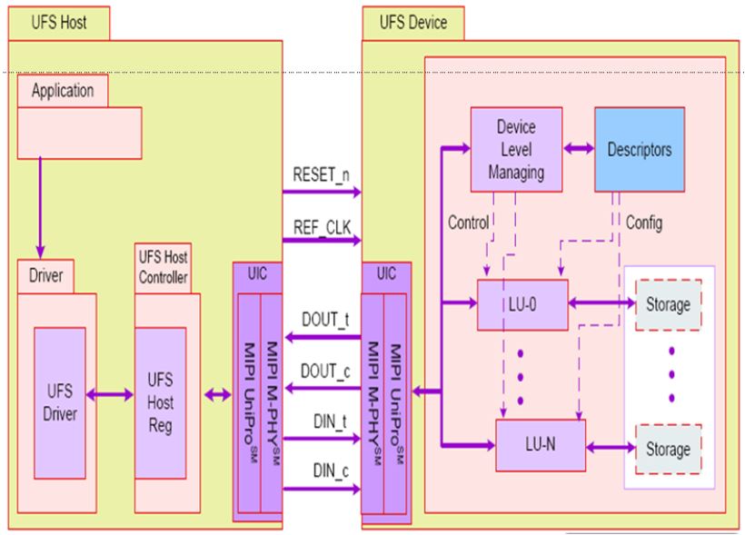
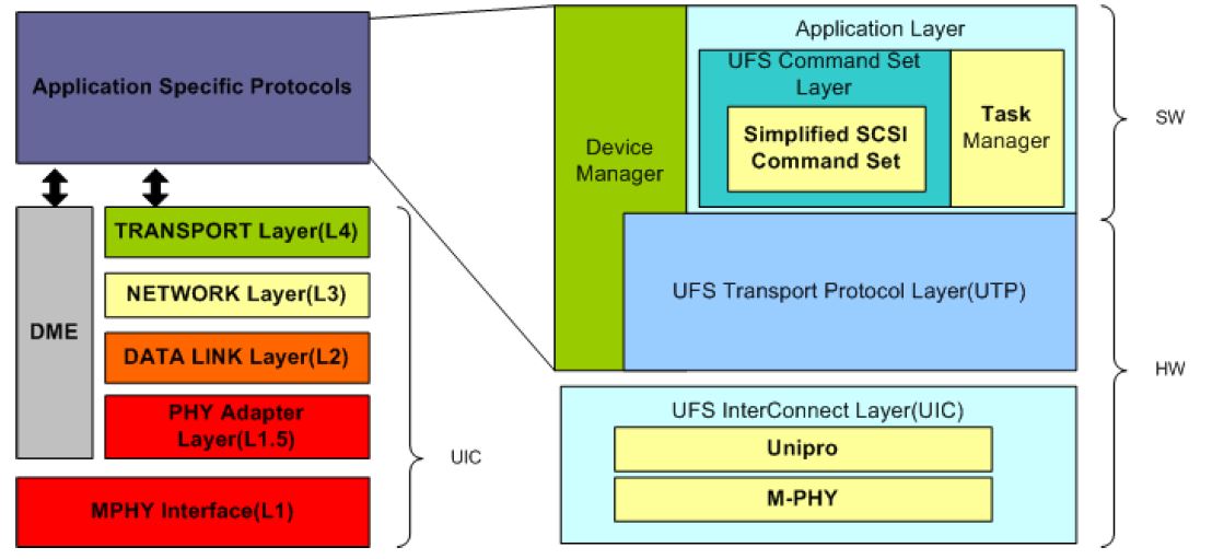
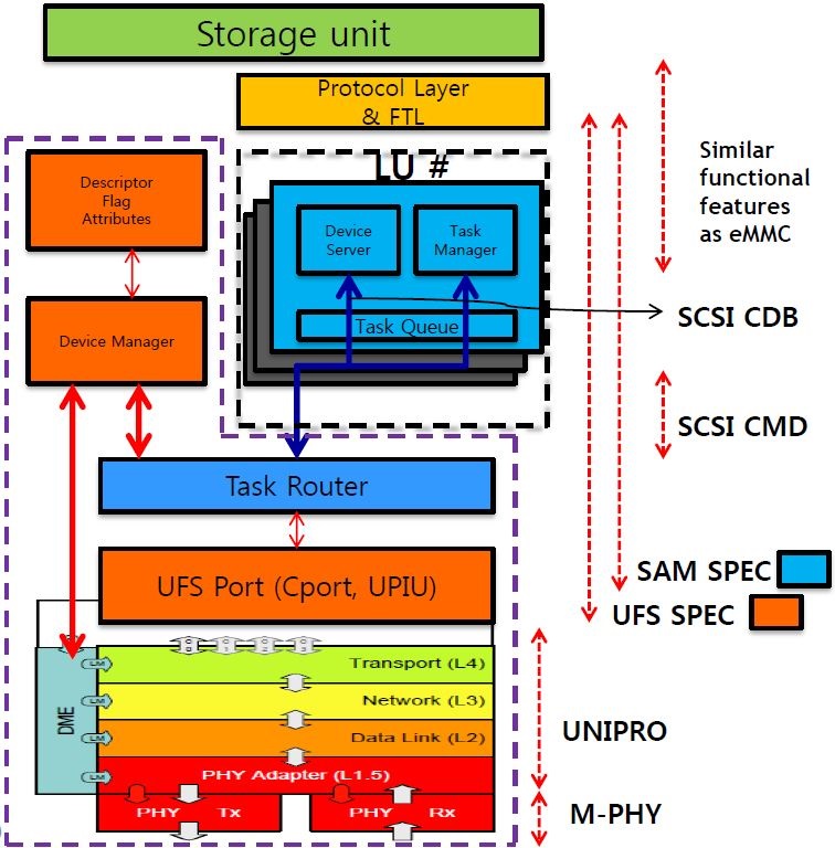
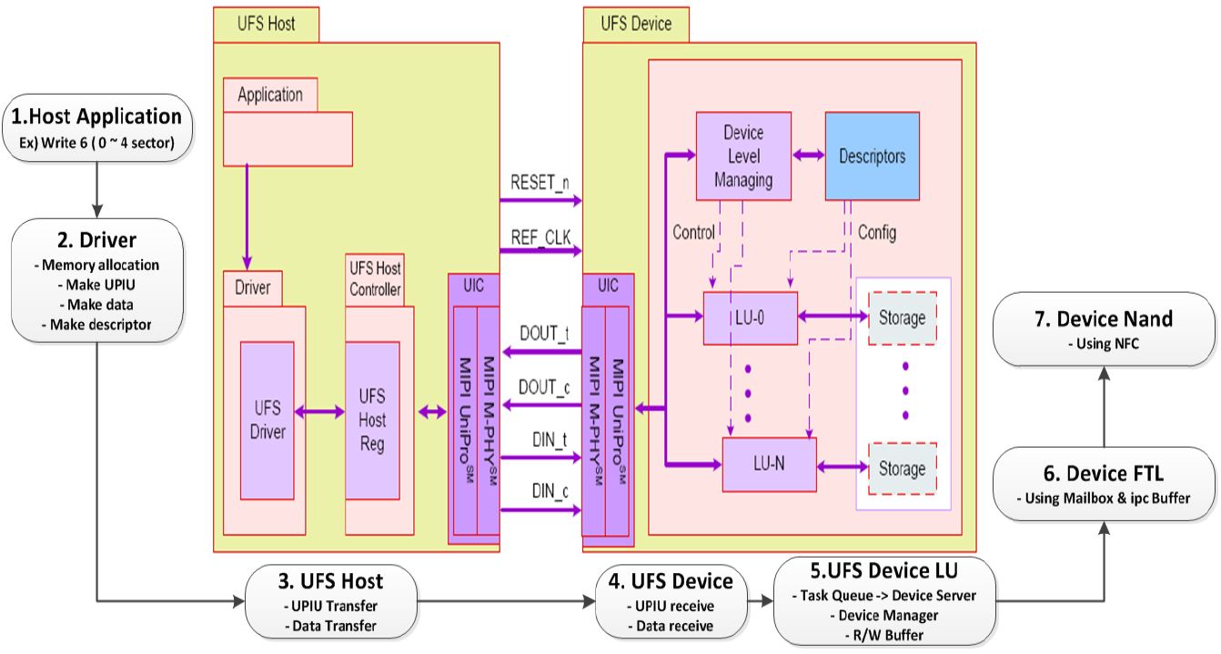
UFS Architecture
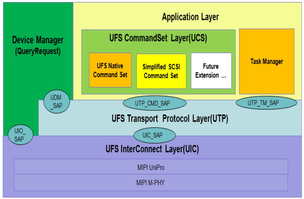
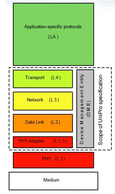
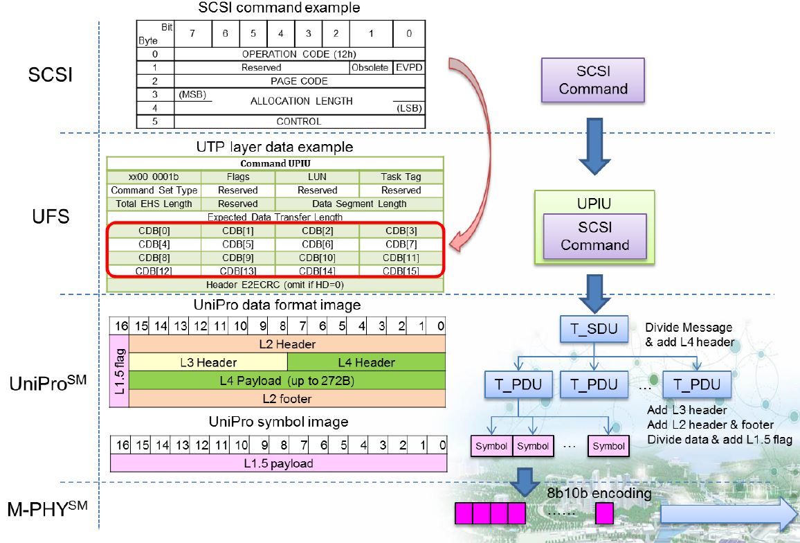
UFS Protocol Layer
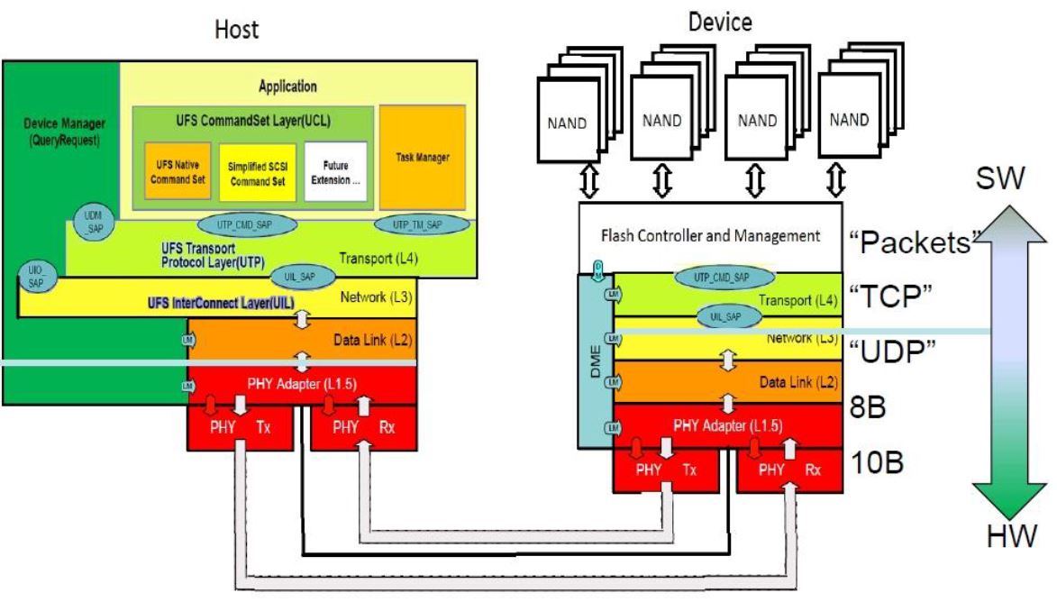
UFS Architecture 2
M-PHY
Each 1LANE
- Normal Speed :
- PWM-G0 ~ PWM-G7 : PWM G1 : 3 ~ 9Mbps
- HS-G1 ~ HS-G3( High Speed )
- HS-G1 : (1.25Gbps or 1.45Gbps)
- HS-G2 : (2.5Gbps or 2.9Gbps)
- HG-G3 : (5Gbps or 5.8Gbps)
- TYPE I : PWM Signaling in UFS 1.0
-
TYPE II : system Clock Reference(NRZ Signaling)
- UFS 1.0(currently) :
- 2.9Gbps(HS-G2) & 1.45Gbps(HS-G1)
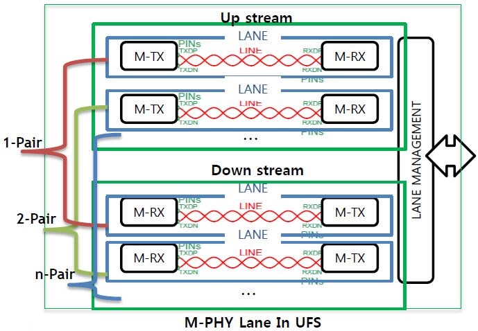
- Extensible by lane increase in pairs
- Each lane’s speed is 2.9Gbps(HS-G2).
- So, ideal bi-directional speed is double of this
- Interface of card type UFS is same as M-PHY of embedded UFS. So, host side implementations (HW, SW) have no difference
UNIPRO ( Unified Protocol )
- Optimized
- For mobile use cases & multiple applications
- Low power & small battery-powered systems
- Enables minimized/extendable implementations
- Reliability with error detection and correction via retransmission simplifies protocol design
- Optimally uses MIPI’s PHY technologies
- Allows aggressive power optimization
- Allows for bandwidth scaling options
- Formal UniPro SDL model available
- UniPro testing specification available
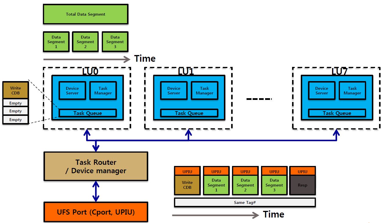
UTP
- highestHW Layer
- SLOT: HW Resource for Command Acceptance
- 32 CMD Slots, 8 Task Slot, 1 Query Slot Each Slot has it’s own DESC.(Description of operation)
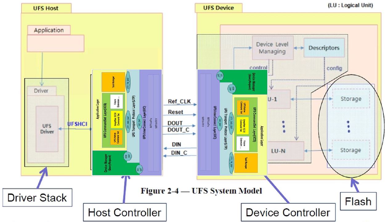
Hardware vs. Software
UFS Standardization
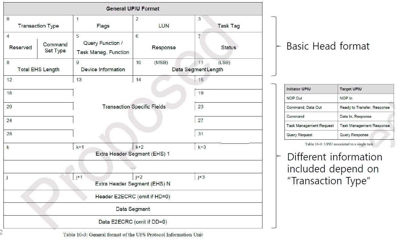
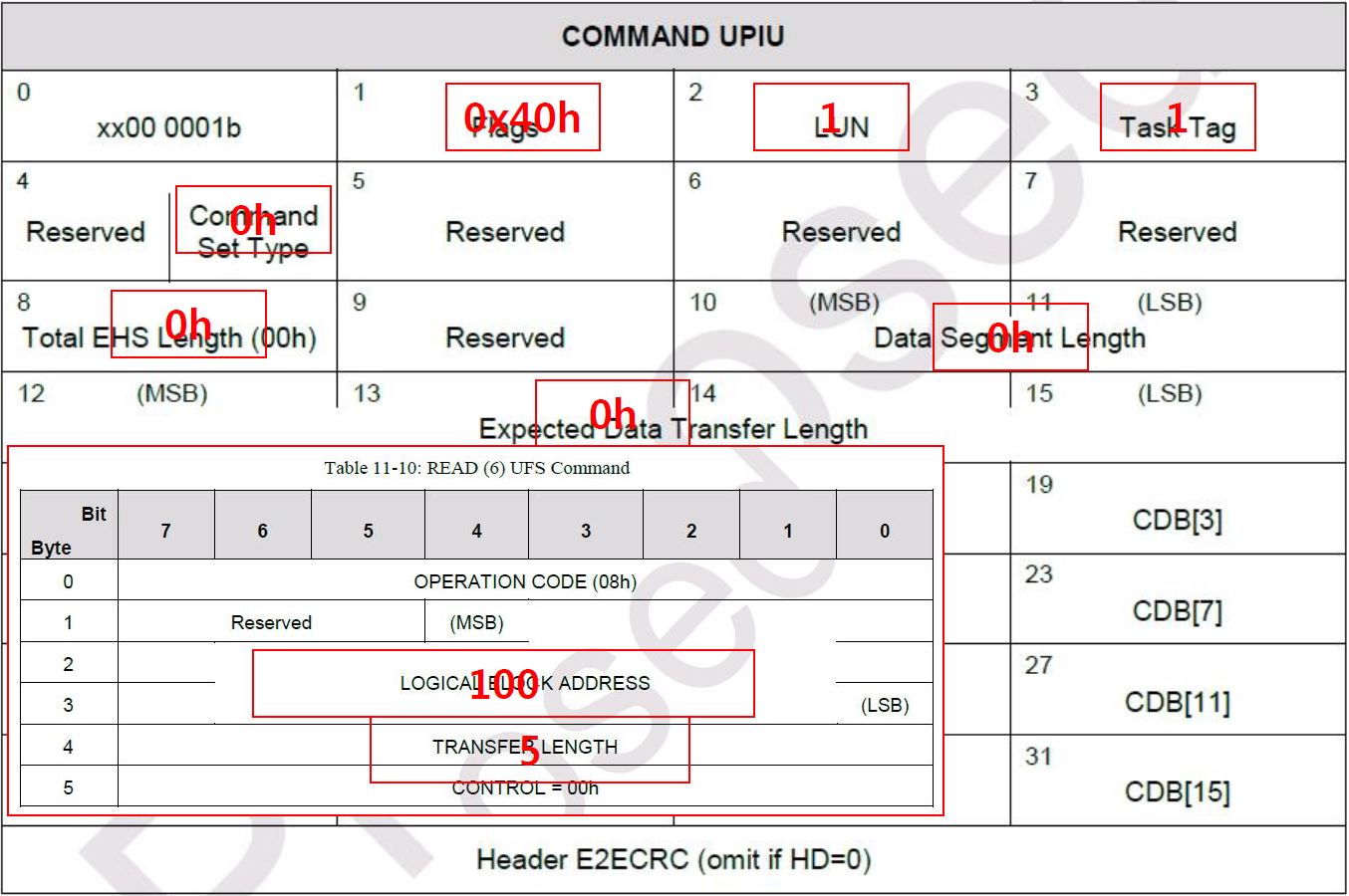
UFS UPIU
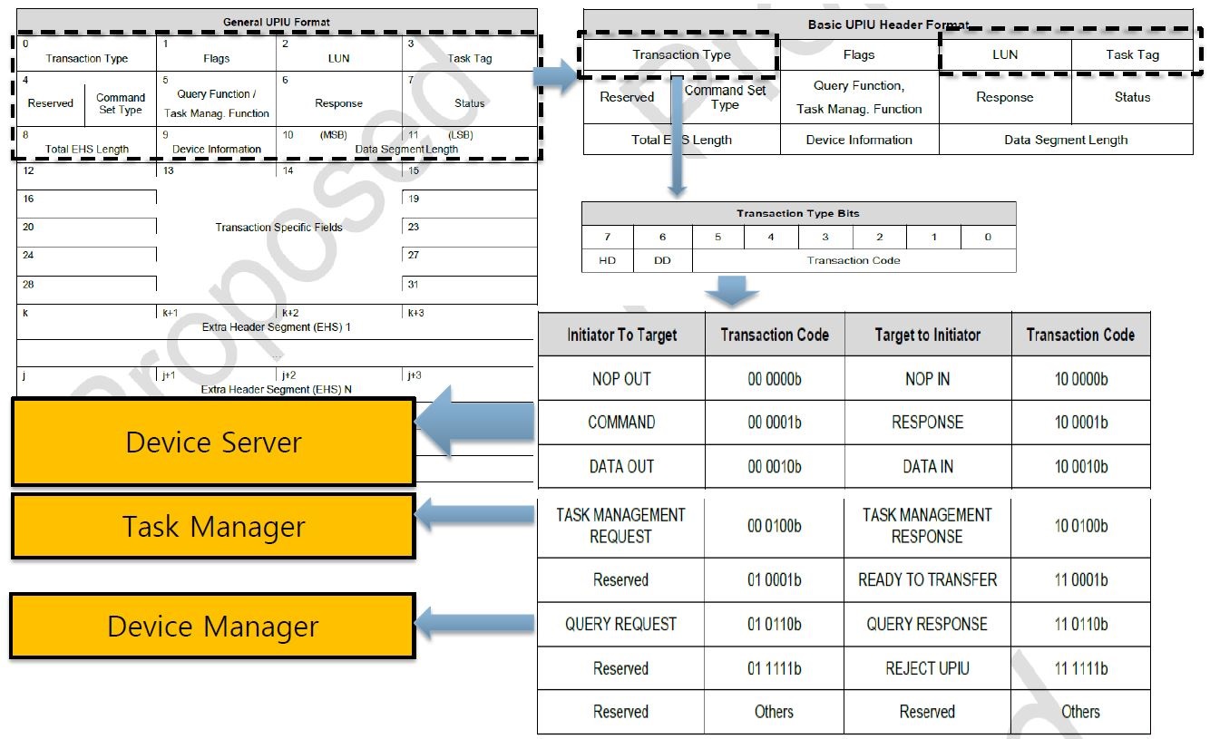
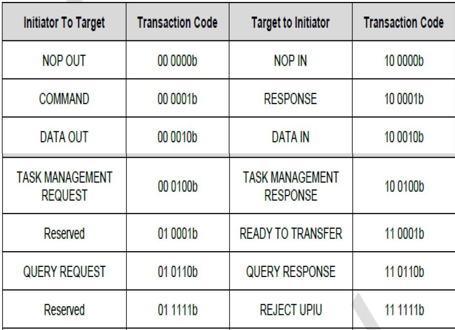
UFS UPIU Transaction Type
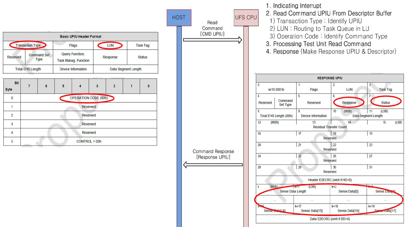
UFS Command Flow
100~104 Sector Read
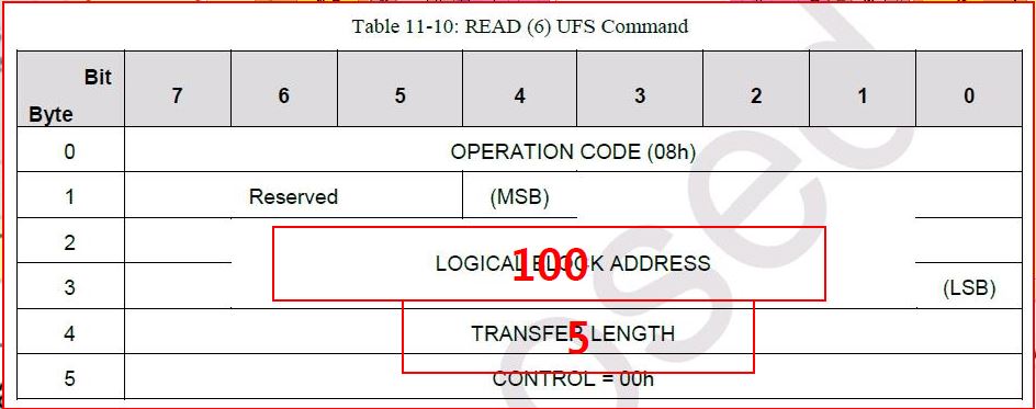
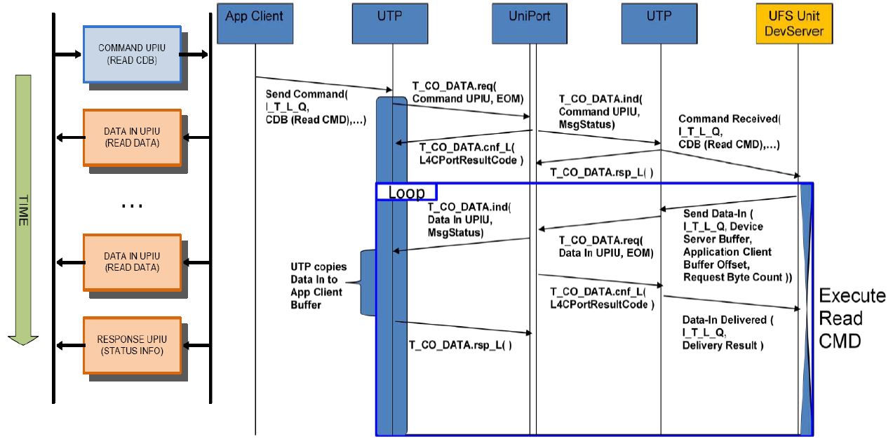
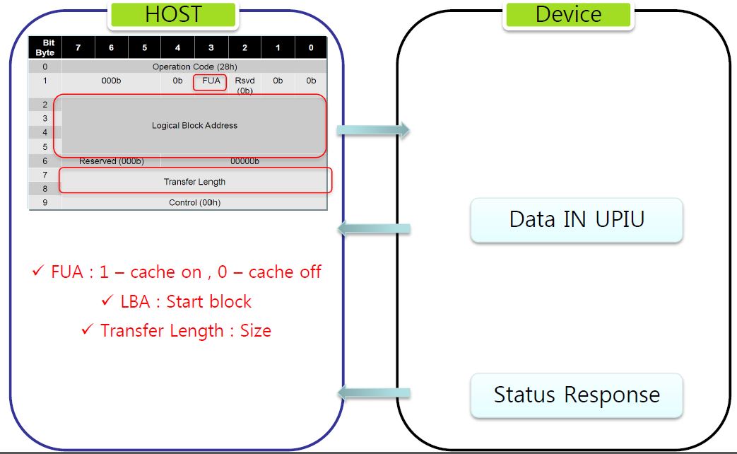
Read Operation Flow
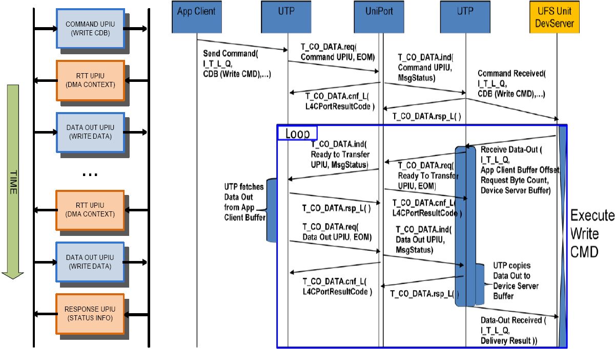
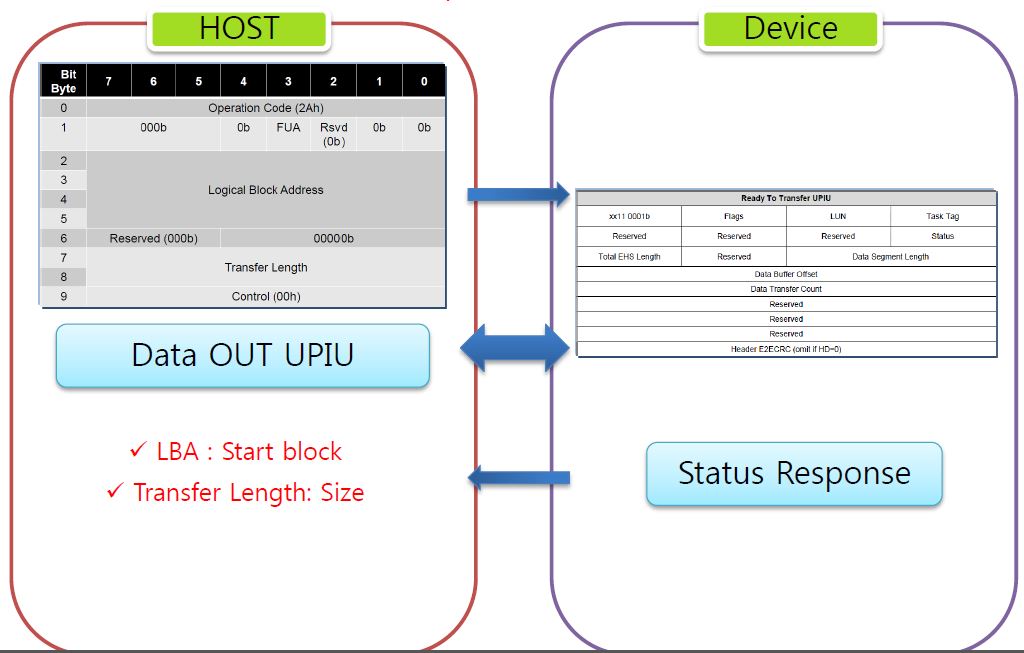
Write Operation Flow
SCSI Command
ScsiCommand Set supported by UFS is based on UFS native commands and Scsiprimary commands spec(SPC-4/SBC-3).
| Commands (CDB Size) | Description | DATA IN UPIU | DATA OUT UPIU |
|---|---|---|---|
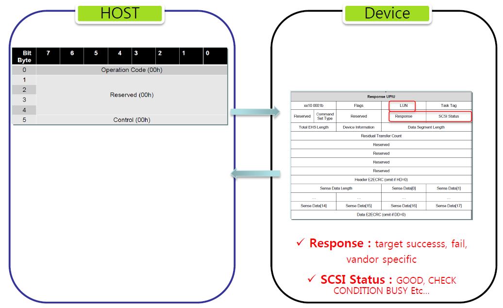
| TEST UNIT READ(6) | Test if device is ready (not for a self-test) | X | X |
| Inquiry(6) | Report device information -type, manufacture, etc | a single Data In UPIU(36byte) | X |
| Request Sense(6) | Report sense data -current status of device | a single Data In UPIU(18byte) | X |
| Read Capacity(10) | Report medium capacity and block sizecan be issued per Logical Unit | a single Data In UPIU(8byte) | X |
| Start Stop Unit(6) | Change power condition or load or eject medium | X | X |
| Read(10) | Transfer data from medium to host | a series of Data In UPIU’s | X |
| Write(10) | Transfer data from host to medium | Ready To Transfer UPIU | a Data OUT UPIU per RTT |
| Read Buffer(10) | Read microcode and other data and tunneling | a series of Data In UPIU’s | X |
| Write Buffer(10) | Transfer microcode and other data and tunnelling | Ready To Transfer UPIU | a Data OUT UPIU per RTT |
| Mode Select(10) | Set parameter , modes, etc | Ready To Transfer UPIU | a Data OUT UPIU per RTT |
| Mode Sense(10) | Report parameters and other device Information -geometry, other | a series of Data In UPIU’s | X |
| Report LUNS(12) | Report the accessible logical unit inventory | one or more Data IN UPIU’s (Most likely one data in UPIU) (8byte+8 x n) (n = LUN) | X |
| Verify(10) | Verify medium data is same as transferred dataTo determine if specific LBA’s are accessible | X | X |
| Format Unit(6) | Format medium into logical blocks, manage medium and defects | Ready To Transfer UPIU | a Data Out UPIU containing the unmber of bytes |
| Send Diagnostic(6) | Perform diagnostic operations on LU or device | Ready To Transfer UPIU | a Data Out UPIU containing the unmber of bytes |
| Synchronize Cache(10) | Recording most recent device data to medium | X | X |
SCSI Command & Operation
- Scsicommands operation by Command Flag Type
-
No Data (Test Unit Ready, Start Stop Unit, Verify)
-
Data from Device (Inquiry, Read6, Request Sense, Read Capacity, Mode Sense, Report LUN)
- Data to Device (Write6, Mode Select, Unmap, Format Unit)
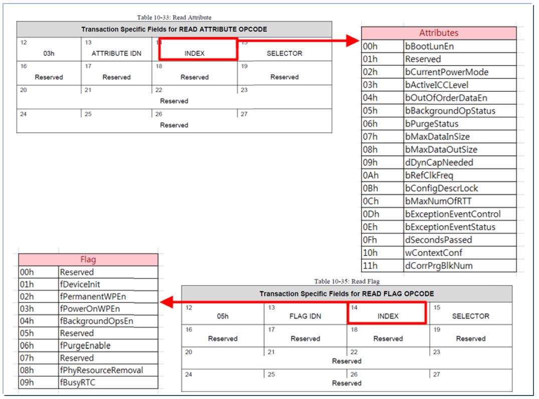
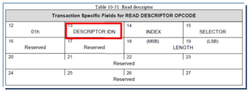
Descriptor & Attribute
- Descriptor : General Configuration for Device-level
- Attribute : Frequently Configurable Range Value
- Flag : Frequently ConfigurableBOOL Value
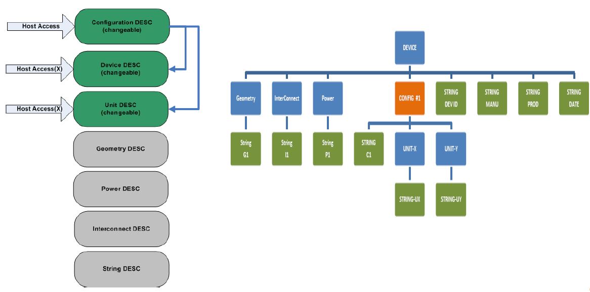
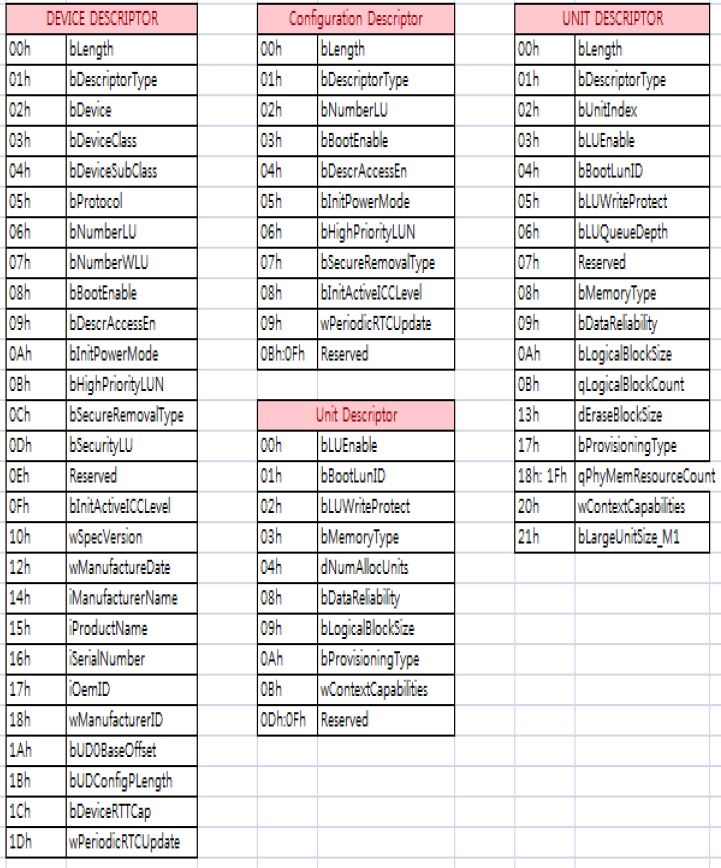
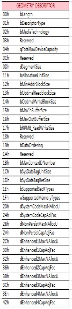
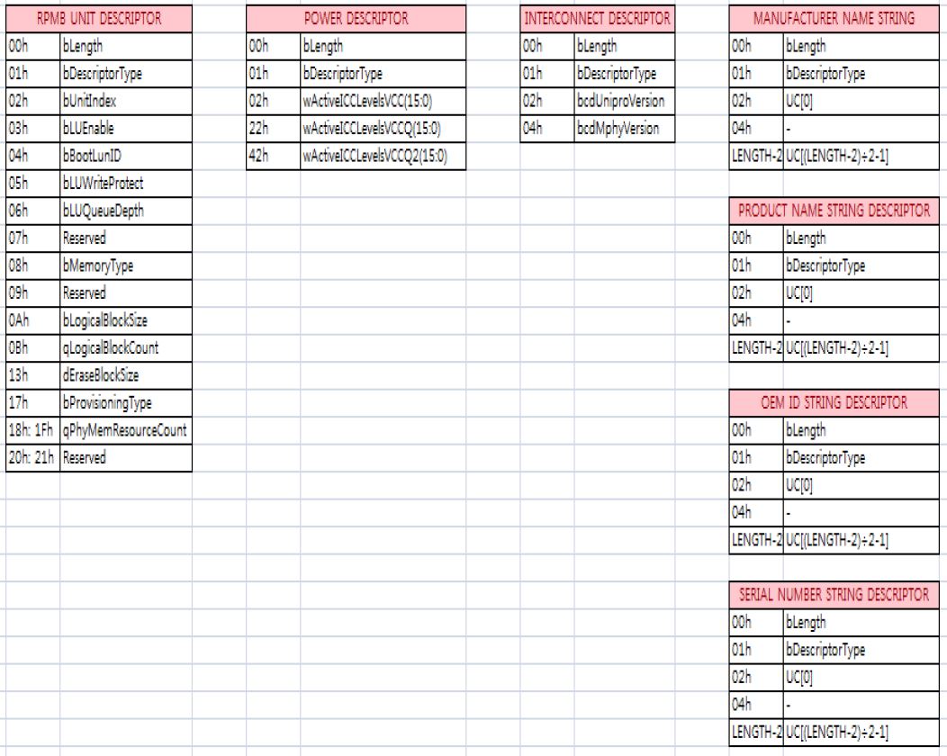
Descriptor
Attribute & Flag