Here is the document about eMMC ppt doc
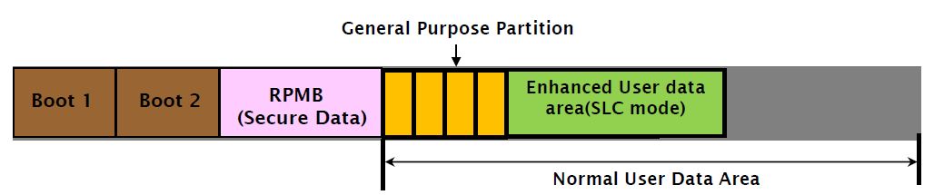
Multi Partition
- eMMC 4.3 2 boot partitions and 1 user data partition
- eMMC 4.4 RPMB partition is added
- 4 general purpose partitions and enhanced user data area can be set in normal user data area
| Partitions | NAND type | Default Size | Remarks |
|---|---|---|---|
| Boot Area Partition 1 | SLC Mode | 128KB | Size as multiple of 128KB (max. 32MB) |
| Boot Area Partition 2 | SLC Mode | 128KB | Size as multiple of 128KB (max. 32MB) |
| RPMB Area Partition | SLC Mode | 128KB | Size as multiple of 128KB (max. 32MB) |
| General Purpose Partitions | MLC “or”Enhanced Area | 0KB | Available size can be seen by following: (EXT_CSD[145]x 82 + EXT_CSD[144]x 81 +EXT_CSD[143]) x HC_WP_GPR_SIZE x HC_ERASE_GPR_SIZE x 512KB byte |
| User Data Area ( Enhanced Area) | SLC Mode | 0KB | Start address multiple of Write Protect Group size |
| User Data Area ( Default Area) | MLC Mode | 93.1% |
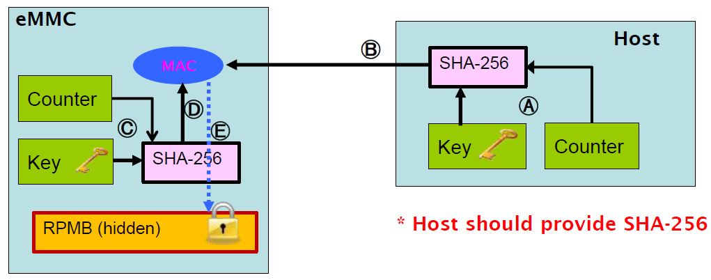
RPMB(Replay Protect Memory Block)
- Only handled by security key (SHA-256)
-
When host tries to access to RPMB
a) Host reads key the counter value to generate MAC (token) using SHA-256 algorithm
b) The host sends the generated MAC to eMMC controller
c) eMMC controller reads the key which was pre-loaded by host and the counter value to generate MAC using SHA-256
d) Compares two MAC. If two keys are identical, RPMB access is allowed
TRIM
- Mark data that is invalid
- Similar to STL_Delete()
- Trim data should be shown as “0” or “1” (by JEDEC)
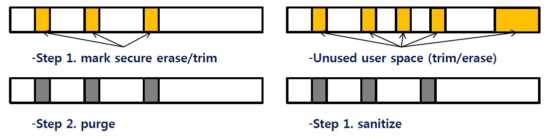
Secure TRIM/Erase
- Secure Trim/Erase
- Step 1 : marks data which is logically deleted
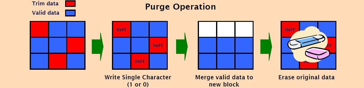
- Step 2 : Actual secure purge operation is executed
-> secure purge: overwrite single character not only to trimed blocks but also to data which was generated by internal operation like wear-leveling, and then erase physically
Secure Trim and Secure Erase are identical except operation unit
- Secure Erase: erase unit is Erase Group size (512KB)
- Secure Trim : step1: sector based size(512byte) step2: purge unit is Write Group size(512KB)
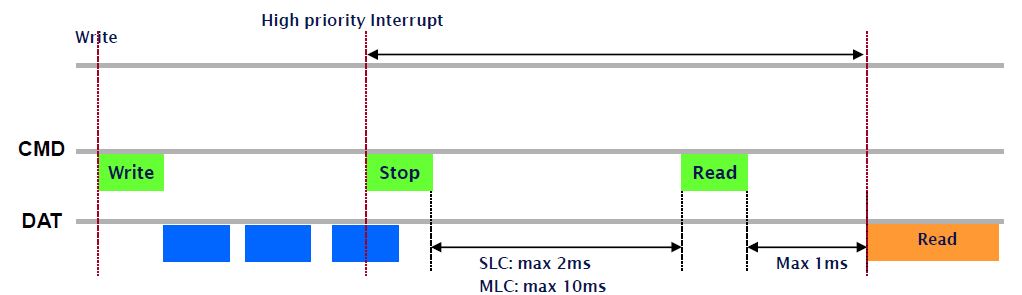
HPI(High Priority Interrupt)
- stops ongoing write operation and then read data within a specific time
- aborts ongoing writing operation by CMD 12
- If read/ write partition is different, additional partition switching time is needed for changing partition
Background Operation
- Host gives free time to the device. During this time device can do housekeeping like merge operation
- Host should check that necessity (4 levels) of background operation
- Helps to improve performance
[Background operation]
| Level | Descriptions |
|---|---|
| 0 | No operation required |
| 1 | Background operation which is not critical |
| 2 | Background operation which impacts on performance |
| 3 | Background operation which is critical |
Data Atomicity
Normal Reliable Write
- The old data that logical address point must retain unchanged until a new data is successfully written to the same logical address
- Reliable write sector (EXT_CSD[222]) : 1 or 255

Enhanced Reliable Write – Sector based Atomicity

eMMC 4.5 Features
| Category | Features | Meaning |
|---|---|---|
| Performance | HS200 | MMC interface speed increases (104200Mbps) |
| Packed CMD | Vectored read/write command (ex. readv/writev) | |
| Cache | Write-back & flush like HDD | |
| Hint | Discard | Mark unused LBA without zero-filling (ex. Deleted files) |
| Context ID | Specify context ID for write command (ex. File, task) | |
| Data tag | Specify data tag for write command (ex. FS meta) | |
| Partition type | Specify GPAP type (system code, non-persistent) | |
| Power-off notify | Host shall not intentionally power-off device without notification | |
| RTC | Send RTC info to device | |
| Dynamic capacity | Device request host for capacity reduction | |
| Security | Sanitize | Purge all unused LBA |
Trim & Discard
Benefits
- Reduce write timeout by reducing garbage collection cost
- Level 3 over-provision
Trim vs. Discard – misalignment handling
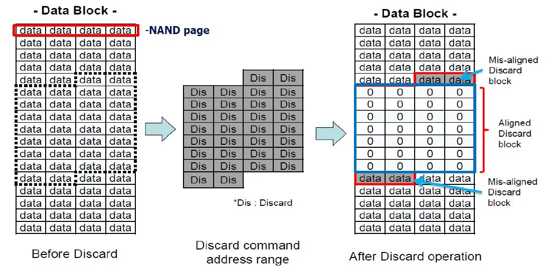
- Trim is useful both for higher throughput and for reducing performance fluctuation
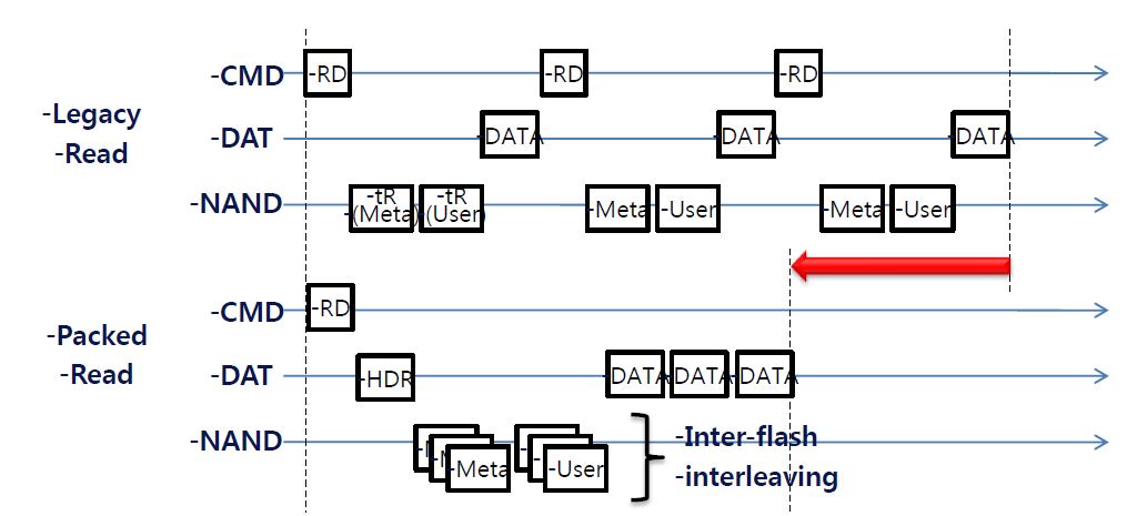
Packed Command
- Reduces # of discrete I/O CMD processing (usually random pattern) higher read and write IOPS
- Internal data processing can be pipelined if there are multiple flash chips that can operate in parallel
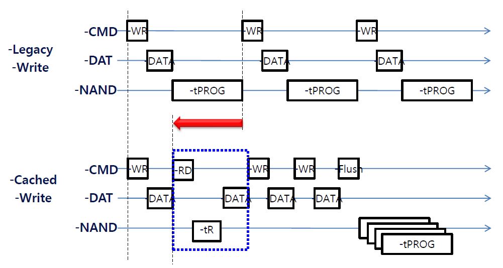
Cache
- Buffers write operations that usually come in burst higher write IOPS, shorter write latency
- May interleave read I/O if there is no ongoing flush operation
Power-off notification
- eMMC FW could use power-off signal for
- marking where the last write operation happened
- flushing dirty metadata of FW into nonvolatile memory
- As a result, eMMC initialization process could be shortened
Sanitize
- Secure erase/trim (4.4) – mark data to be securely deleted and purge at once
- Sanitize (4.5) – purge unused data at once may take huge time for completion